

Electromagnetic Converter
Product Overview
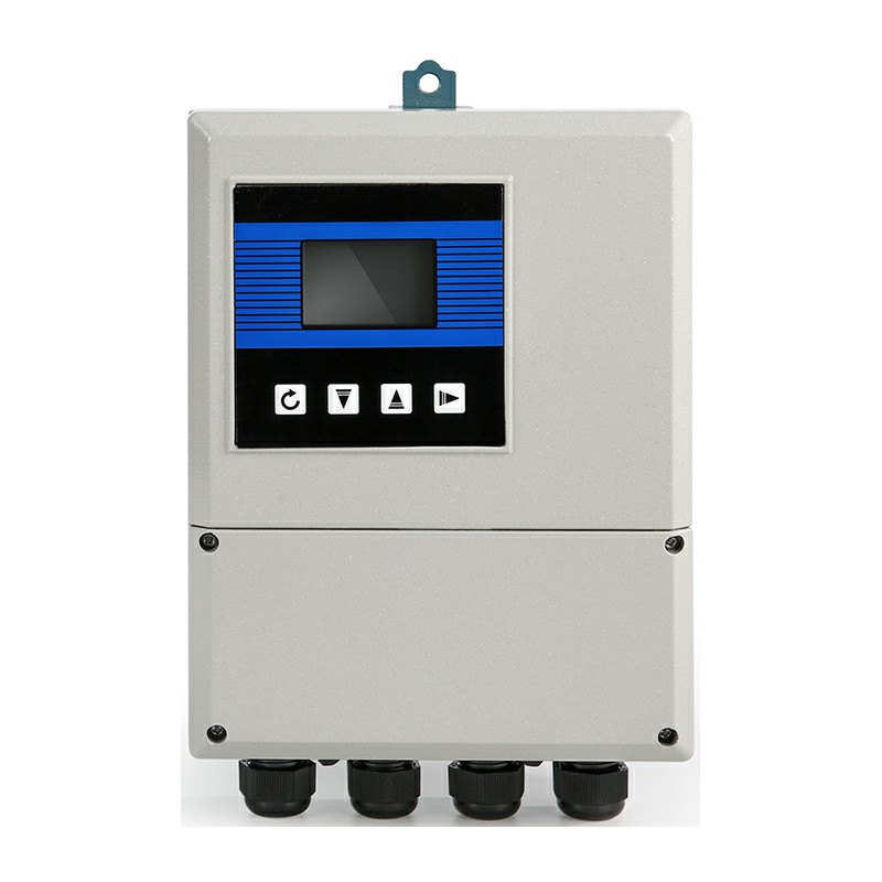
The Electromagnetic Converter is a microprocessor-based signal transmitter engineered to process low-level electromotive force (EMF) signals from electromagnetic flow sensors. It energizes the sensor's magnetic coils, extracts flow-proportional voltage via advanced synchronous sampling, and converts the data into industry-standard analog, pulse, or digital communication outputs. Designed for panel-mount, remote wall-mount, or compact integration, this unit handles bidirectional flow measurement, empty-pipe detection, and real-time self-diagnostics without signal degradation in harsh industrial environments.
-
![Battery-Powered Electromagnetic Transmitter]() Battery-Powered Electromagnetic TransmitterThe KFD9000 Series (MFLD Series) Battery-Powered Integral Electromagnetic Flow Converter is an industrial-grade, ultra-low-power flow transmitter engineered specifically for municipal water...read more
-
![Integrated Type Electromagnetic Converter]() Integrated Type Electromagnetic ConverterThe Integrated Type Electromagnetic Converter is an intelligent electronic unit that pairs with electromagnetic flow sensors to measure the flow rate of conductive liquids. supports a wide range...read more
-
![Remote Type Electromagnetic Converter]() Remote Type Electromagnetic ConverterThe Remote Type Electromagnetic Converter is an intelligent electronics unit that pairs with electromagnetic flow sensors to measure the flow rate of conductive liquids. It features a backlit LCD...read more
-
![Battery-Powered Electromagnetic Converter]() Battery-Powered Electromagnetic ConverterBattery-powered electromagnetic flow meters offer cable-free operation and easy installation in remote or hard-to-access locations without external power sources.read more
● Wide Application...


Measurement & Testing Principle
The device operates on Faraday's Law of Electromagnetic Induction.
When a conductive fluid (minimum conductivity min 5 uS/cm) flows through the magnetic field generated by the sensor coils at an average velocity v, a proportional voltage E is induced:E = k * D * B * v(where k is the meter constant, D is the pipe diameter, and B is the magnetic field strength).
Signal Processing Pipeline: The converter samples the low-amplitude mV signal using a dual-frequency square-wave excitation method. Low-frequency excitation eliminates electrochemical polarization noise, while high-frequency excitation ensures zero-point stability and rapid dynamic response. Analog signals pass through a high-input-impedance preamplifier (greater than 10 to the power of 8 ohms), a 24-bit Analog-to-Digital Converter (ADC), and digital filtering algorithms before microprocessor scaling.
Product Types & Configurations
Series EC-100 (Compact / Integral Type)
Direct-mounted onto the flow sensor neck. Best suited for accessible pipeline installations with local LCD visualization.
Series EC-200 (Remote Wall-Mount Type)
Separated from the sensor by up to 100 meters of signal/excitation cable. Designed for high-vibration pipelines, sub-surface manholes, or high-temperature fluid environments.
Series EC-300 (Hazardous Area Type)
Housed in a robust metal enclosure designed for chemically demanding or industrial process zones.
Key Features
Dual-Frequency Excitation: Eliminates slurry noise and electrochemical interference in heavy pulp or mining slurries.
High Input Impedance: 10^8 ohms preamplifier circuit prevents loading effects on low-conductivity fluid measurements.
Dynamic Empty-Pipe Detection: Integrated electrode impedance monitoring prevents false readings during partial pipe fill conditions.
Bi-Directional Measurement: Independent forward and reverse totalization with configurable pulse outputs.
Galvanic Isolation: Optical isolation (greater than 2000V) between power supply, signal input, and output terminals to withstand industrial surge currents.

Technical Specifications
|
Parameter Category |
Specification Details |
|
Excitation Frequency |
6.25 Hz, 12.5 Hz, 25 Hz (selectable based on fluid characteristics) |
|
Measurement Accuracy |
Plus or minus 0.5 percent of reading (standard), Plus or minus 0.2 percent of reading (optional high-precision calibration) |
|
Repeatability |
0.1 percent |
|
Min. Fluid Conductivity |
Min 5 uS/cm |
|
Analog Output |
4-20 mA active/passive (load resistance max 750 ohms) |
|
Digital Outputs |
Pulse / Frequency output (max 5 kHz), Alarm relay outputs (solid-state) |
|
Communication Protocols |
HART, Modbus RTU (RS485), Fieldbus options available |
|
Power Supply |
85-265 VAC (50/60 Hz) or 20-32 VDC |
|
Enclosure Material |
Die-cast aluminum alloy with corrosion-resistant polyurethane powder coating |
|
Ingress Protection |
IP65 (Integral type), IP67/IP68 (Remote transmitter housing) |
|
Ambient Temperature |
-25 C to +60 C |
|
Operating Humidity |
5 percent to 90 percent RH (non-condensing) |
Applications
Municipal Water & Wastewater
Effluent monitoring, sludge flow measurement, chemical dosing control.
01
Chemical & Petrochemical
Corrosive acid/alkali transfer, reaction tank feed monitoring.
02
Mining & Mineral Processing
High-solid abrasive slurry transport in copper/gold ore processing lines.
03
Pulp & Paper
Black liquor, white liquor, and paper stock flow metering.
04
Agriculture & Irrigation
Large-scale canal and pipeline water abstraction metering.
05
Installation & Operating Considerations
Grounding Requirements
Proper grounding rings or grounding electrodes are mandatory to eliminate common-mode stray currents. The converter housing must be tied to a dedicated earth ground (max 10 ohms).

Cable Selection
For remote installations (EC-200), use dual-shielded specialized cables (excitation core plus signal twisted pair) to prevent cross-talk and RF interference. Do not run signal cables parallel to high-voltage power lines.

Straight Pipe Runs
Ensure upstream min 5D and downstream min 2D straight pipe clearances relative to the sensor to maintain velocity profile symmetry.

Zero-Point Calibration
Perform zero adjustment only when the pipeline is completely filled with static, zero-velocity fluid and the system has reached thermal equilibrium.
Manufacturing & Quality Control
SMT Assembly
Circuit boards are assembled using automated Surface Mount Technology (SMT) lines with 0402 passive component precision and automated optical inspection (AOI).
Conformal Coating
PCBs receive an industrial-grade acrylic conformal coating to protect circuitry against condensation, hydrogen sulfide (H2S), and humidity.
Burn-In Testing
100 percent of manufactured converters undergo a 72-hour thermal burn-in cycle at +55 C under powered operating conditions to screen out semiconductor failures.
Calibration & Traceability
Each unit is calibrated on a gravimetric/master-meter water flow calibration rig, generating an individual calibration coefficient sheet.
Selection Guide
Determine Sensor Compatibility
Verify that the coil resistance (typically 10 to 100 ohms) and electrode signal range match the converter's input specifications.
Select Mounting Style
Choose Integral (EC-100) for standard indoor utility panels; choose Remote (EC-200) if ambient temperatures exceed +60 C, vibration exceeds 1.5g, or the sensor is submerged in a pit.
Confirm Power & Output Requirements
Match plant control architecture (e.g., 24VDC power with HART over 4-20mA, or RS485 Modbus for multi-drop PLC networks).
Environment Check
Specify appropriate enclosure protection levels if installed in harsh or outdoor exposed atmospheres.
Frequently Asked Questions
Dalian Yheng Technology Co., Ltd. is one of the leading electromagnetic converter manufacturers and suppliers in China, also supports customized service. We warmly welcome you to buy high quality electromagnetic converter in stock here from our factory. Contact us for more details.
Integrated Type Electromagnetic Converter, electromagnetic converter, Battery Powered Electromagnetic Converter